Get Advanced Flare Monitoring System for Industrial Safety and Compliance
Agile Microsys offers a full flare monitoring solution for industries operating flare stacks that are designed to meet their needs professionally. Our flare monitoring system ensures constant, real-time tracking to uphold safety, meet compliance standards, and streamline operations. The modern flare monitoring cameras as well as the FLIR monitor technologies allow us to give precise and valuable information that will meet the requirements of your facility.
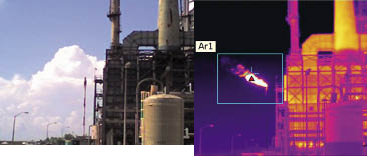
FLIR thermal imaging cameras
- Monitor combustion to reduce unburned emissions
- Quickly detect combustion loss with visual and audio alerts
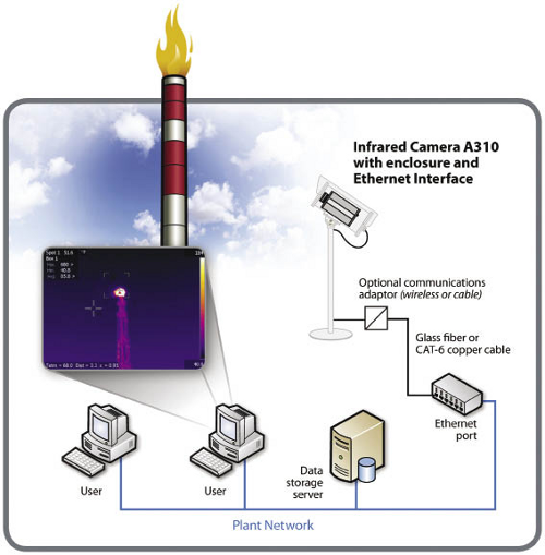
- Enable remote visual monitoring on a PC or TV screen
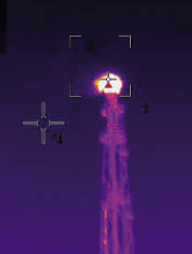
- Offer precise temperature measurement
- Alert plant management through email and intranet links
- Connect to central control rooms via Ethernet
- Operate around the clock, every day, and in all weather

Key Advantages of Our Flare Monitoring System
Our strategy of flare monitoring and management is the most efficient and practical way to ensure the safety of operations. Here is why our system stands out:
- Reliable and Real-Time Monitoring: The hardware and software that form our flare monitoring system are state-of-the-art and provide real-time analysis of emissions from the flare stack. Our FLIR monitors record in high-definition visuals. Thus evaluating deviations has become more manageable. It also helps to minimize the occurrence of downtime.
- Seamless Integration with Flare Stack Monitoring: Our solutions are compatible with currently adopted structures and enhance flare stack monitoring. Whether it is a new installation or an upgrade, our flare stack monitoring system will meet your requirements.
Cutting-Edge Features of Our Flare Monitoring Camera
The characteristics of this camera are:
- Enhanced Visuals with FLIR Technology: Programs based on our flare monitoring cameras include FLIR monitors. This ensures the documentation of flare operations regardless of weather conditions.
- Automated Alerts for Prompt Action: You can get alerts right away to be able to act on any problem. Flare stack management becomes easier and less risky for your team owing to this feature.
- Robust and Reliable Design: Designed to withstand all sorts of conditions in a production line, our flare stack monitoring system offers rugged reliability at work.

Benefits of Choosing Our Flare Monitoring System
You will get these perks if you choose our system:
- Enhanced Safety: Reduce the level of danger that comes with emissions by constantly checking on them.
- Regulatory Compliance: Stand out from the competitors and have trustworthy data for your reporting.
- Cost Efficiency: Reduce operational costs through early detection and timely intervention.
Why Our Flare Monitoring System is the Right Choice
At Agile Microsys, we bring industry expertise and top-tier technology to flare monitoring. Our flare stack monitoring solutions are not just products—they are instruments that make you and your facility safer, more efficient, and completely compliant. You can rely on us to provide you with long-term solutions for the security of your operations.

Empowering Safer, Smarter Operations with Precision Flare Monitoring
Instead of merely offering a monitoring system, at Agile Microsys we promise you the safety of your property and family. We provide cutting-edge flare monitoring solutions which can be much more than a compliance check for your team, by giving them all the tools, accurate data, and dependability that comes from using the latest in technology. Turning data into insights in real-time with appropriate alerts, you get precisely what matters to you most – making your operations safe, sustainable, and effective.
Find out how our bespoke flare monitoring system will revolutionize your outlook on safety and compliance. Let us build a future where safety is not just a priority—it is a promise.

